Heat Transfer

Intended Learning Outcomes
At the end of this lecture student will be able to:
- Define heat and heat transfer
- Explain the different mechanisms of heat transfer
- Recall the applications of heat transfer
- State Fourier’s law with applications
- Derive equation for compound resistance for conduction
- Differentiate between natural and forced convection
- State the differences between black body and grey body
- State Stefan Boltzamann law for radiation
- Contrast between heat exchangers and heat interchangers
- Classify heaters according to the mode of heat transfer
- Describe the construction and working of Tubular heater
- Explain the working of multipass heater
- Draw and describe the working of few heat interchangers
PDF Available on bottom of the blog
Introduction
Heat
Heat is a form of energy. According to the principle of thermodynamics whenever a physical or chemical transformation occurs heat flow into or leaves the system.
A number of sources of heat are used for industrial scale operations steam and electric power is the chief sources to transfer heat.
It is essential to cover steam without any loses to the apparatus in which it is used.
The study of heat transfer processes helps in be signing the plant efficiently and economically
Heat Transfer:
Work is one of the basic modes of energy transfer in machines the action of force on a moving body is identified as work.
The work is done by a force as it acts upon a body moving in the direction of the force. Work transfer is considered as occurring between the system and the surroundings work is said to be done by a system is the sole effect on things external to the system can be reduced to the raising of a weight.
Applications
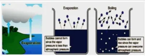
Evaporation Heat is supplied in order to convert a liquid into a vapour, which is subsequently removed. This process is used for preparing vegetable extracts.
A construction similar to shell and tube heat exchanger is employed in evaporators. The heat flow can be quantified so as to estimate the efficiency of process.
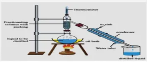
Distillation
Heat is supplied to a liquid mixture for converting the liquid into vapour so that the individual vapour components are condensed at another place. In case of steam distillation, steam will be in direct contact with the material.
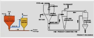
Drying
In the production of tablets, heat is passed through a carrier gas over a bed of wet solid mass for achieving drying. In case of spray drying, heat is supplied to the solutions and suspensions (as in case of production of milk products).
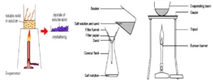
Crystallization
Saturated solution is heated to bring about super saturation, which promotes thee crystallization of drugs. On the other hand, removal of heat (cooling) from a saturated solution also facilitates crystallization as in case of purification of bulk drugs.
Sterilization
For the sterilization of pharmaceuticals, autoclaves are used with steam as a heating medium. Dry heat is used for the sterilization of glass apparatus and other containers.
In addition, a number of other processes, such as boiling, exsiccation, sublimation and fusion, also use heat.
In a laboratory setup, number of equipment involving heat is used. A few examples are air-ovens, incubators, dryers, refrigerator’s etc.
On industrial scale, equipment is used for applying heat, removing heat and preventing heat loss. The basic principles involved in heat transfer are properly for maintenance and efficient working of the equipment.
Modes of Heat Transfer

What is Conduction?
How are the particles arranged in a solid, a liquid and a gas?

Solids Liquids Gases
Conduction is the transfer of energy from more energetic particles of a substance to adjacent less energetic ones result of interaction between particles.
It can be understood from the Fourier law of Conduction
Why are metals good thermal conductors?
There are delocalised electrons (‘free’ electrons) in metals
These free electrons can move freely throug hout the metals
When heated, these free electrons gain kinetic energy and move from the h o tter end to the colder end, carrying energy with them.
This process is much faster than conduction by the vibration of the molecules.
Conduction is the process by which heat is transmitted through a medium from one particle to another.

When heat flow in a body is achieved by the transfer of the momentum of individual atoms or molecules without mixing such a process is known as conduction
For example, flow of heat through the metal shell of a boiler takes place by conduction as far as solid wall or shell is considered.
No mixing is involved. Conduction is limited to solids and fluids whose movement is restricted
What is Convection?
What happens to the particles in a liquid or a gas when you heat them?
The particles spread out and become less dense
Convection is the mode of energy transfer between a solid surface and the adjacent liquid or gas that is in motion, and it involves the combined effect of conduction and fluid motion. The faster the fluid motion, the greater the convection heat transfer
Convection is the process by which heat is transmitted from one place to another by the movement of heated particles of a gas or liquid.
When a liquid is heated, it expands and this lowers its density.
The less dense liquid rises and its place is taken by more dense colder liquid. This movement of liquid forms convection currents.
Molecules in fluids are furtherapart and have negligible cohesive force.
Convection currents are set up much faster in gases t h an in liquids because of the extremely low cohesive forces existing between the molecules of the gases.

For example, heating of water by a hot surface (coil type water heater) is mainly by convection. Convection is restricted to the flow of heat in fluids (i.e. liquid and gases).
Convection is restricted to the flow of up almost daily in the atmosphere. These are responsible for winds, land and sea breezes, ocean current etc.
Types of Convection
- Natural convection: Natural convection occurs whenever heat flows between a solid and fluid, or between fluid layers.
As a result of heat exchange, Change in density of effective fluid layers taken place, which causes upward flow of heated fluid.
If this motion is associated with heat transfer mechanism only, then it is Natural Convection.
- Forced convection: Mixing of hot and cold parts of the fluid through some external stirring, like a fan or pump. If this motion is associated by mechanical means such as pumps, gravity or fans, the movement of the fluid is enforced.

Radiation
- Heat transfer through vacuum is called thermal radiation. All bodies absorb and emit radiation.

An electric bulb in a room produces both light and radiant heat. The radiant heat is absorbed by the materials in the room, which in turn give out radiant heat of lower energy.
How Does Heat Travel through Space?
- The Earth is warmed by heat energy from the Sun.
- How does this heat energy travel from the Sun to the Earth?

Infrared waves
- There are no particles between the Sun and the Earth, so the heat cannot travel by conduction or by convection.
- The heat travels to Earth by infrared waves. These are similar to light waves and are able to travel through empty space.
Emission Experiment

- The shiny metal container would be the warmest after ten minutes because its shiny surface reflects heat Radiation back into the container so less is lost. The dull black container would be the coolest because it is the best at emitting heat radiation.
- When heat flows through space by means of electromagnetic waves, such energy transfer is known as radiation.
- For example, a black surface absorbs most of the radiation received by it. Simultaneously the absorbed energy is quantitatively transferred into heat. Fused quartz transmits all the radiation that strikes it, while a polished opaque surface or mirror will reflect most of the radiation that strikes it.
- Solar water heaters, solar water heaters, solar cockers, microwave ovens, microwave cockers, solicitor baths etc. are few examples in which radiation is utilized for producing heat.
- In general, these mechanisms may operate simultaneously. For example, in ovens hot air is circulated by fan, so as to transfer heat by forced convection. Simultaneously,
Conduction
Heat can flow only when there is a temperature gradient, i.e. heat flows from a hot surface to a cold surface. The rate of conduction through solid can be studied easily, since it is the sole phenomenon. The basic law of heat transfer by conduction can be written in the form of rate equation as follow:
Rate=Deriving Forces / Resistance ………………………..(1)
The driving force is the temperature drop across the solid surface. The greater the temperature drop, the greater will be the rate of heat flow.
The flow of heat will also depend on the conductivity of the materials through which it is flowing. For example, conduction of heat is faster through an iron rod than through a wooden log.
This factor is represented by the team resistance, which can be quantitatively expressed by Fourier’s law.
Resistance = Thickness of the surface (m) / meanproportionality constant wm.K x Area of surface (m2)
= L/kmA………………………(2)
Equation (2) for resistance can be obtained from the Fourier’s law.
Fourier’s law states that “the rate of heat flow through a uniform material is proportional to the area and the temperature drop and inversely proportional to the length of the path of flow”
The Fourier’s law may be mathematically expressed as:
![]()
Derivation:- Fourier’s law can be applied to a metal wall through which the conduction of heat is taking place. The characteristics are as follows:
Area of Wall = A,m2
Thickness of the wall = L, m
Definite and higher temperature=t1, K
Face of the wall is maintained at a lower,
But uniform temperature=t2, K
The heat flow will be at right angles to the plane A and is assumed to be in a steady state. Consider a thin section of thickness at an intermediate point in the wall. This section is parallel to the plane; A for this section, Fourier’s law may be applied as given below:

Q=heat transferred, J
θ =Time, s
K=proportionality constant/m.K
t=temperature,
K The constant, k, is a function of temperature, but independent of length. The minus sign indicates the decrease in temperature in the direction of flow
The constant, k, is a function of temperature, but independent of length. The minus sign indicates the decrease in temperature in the direction of flow. In equation (4), (dt/dL) represents the temperature gradient. For a steady state heat transfer, equation (4) changes to:
DQ/dθ = Constant = q = k.A .dt/dL

Figure : Heat transfer through a metal wall by conduction
The temperature difference in the intermediate section is not known. But temperatures at the two faces of the wall are known.
The area, A May vary with L, but is independent of temperature.
By separating the variable, equation (5) can be written as
qdL/A= -kdt ——– (6)
Integrating equation (6) between the limits
L=0 when t = t1 and
L=L (total thickness) when t=t2,

Where km = meanproportionality Constant ,
w /m.K
In steady state heat transfer, q remains constant. In equation (3) the term
Applications
- Thermal conductivity is the reciprocal of thermal resistance. Thermal conductivity of a solid is expressed in terms of k as per equation (3).
- The coefficient of thermal conductivity is the quantity of heat that flows across a unit surface area in unit time, when the temperature drop is unity.
- The coefficient of thermal conductivity depends upon the material with which the body is made and upon its temperature.
Thermal conductivities of some substances are given in table -1.
Table -1 Thermal Conductivities of Some Metals From table1, the following conclusions can be drawn.
Materials Thermal Conductivity, w/make
Copper 379.0
Silver 57.0
Steel 43.0
Aluminium 24.2
Stainless Steel 17.0
Glass (borosilicate) 1.0
Building bricks 0.69
Water 0.62
Air 0.03
Double steel plate sand divider 0.207
Powdered iron 0.0533
Aerocat Catalyst 0.163
Table salt 0.168
Powdered coal 0.070
- Thermal conductivities of liquids and gases are very small compared to most of the solids. In other words, the resistance offered by liquids and gases is high as far as the conduction is concerned.
- In case of steam jacketed vessels, the kettle (inner surface), must have good conductivity so that maximum amount of heat passes from the steam to the contents.
- The high thermal conductivity of copper suggests that it is a suitable material for the construction of the kettle. • At the same time the metal used for jacket (outer surface) must have minimum conductivity to prevent loss of heat by conduction and radiation.
- The low thermal conductivity of iron suggests that it would be suitable material for the construction of the jacket. Such materials should be resistant to solvent or chemical action of liquid.
- For the construction of evaporators and tubular heat exchangers thermal conductivity values are helpful. Thermal conductivity is very sensitive to changes in chemical composition and temperature and therefore the above values cannot be applied to all situations.
Compound Resistance in Series
Consider a flat wall constructed of a series of layers as in figure.
The characteristics are:
Thickness of the three layers=L1, L2 and L3, m
Conductivities of materials of which layers are made =k1, k2 and k3, w/m.K
Area of the entire wall=A,2
Temperature drops across three layers

According to Fourier’s law, individual resistances are descried y equation (2). These are incorporated in equation (9) to get
R = L1/ k1A+ L2 / k2A + L3/k3A
Since entire heat must pass through the resistances in series, heat q can be written as:
q = q1 + q2 + q3 (11)
Using the principles of conduction, the rate of heat transfer, q, may be expressed as:
∆ t
q = ———————- (12)
R1 + R2 + R3
The contributions of temperature drops to the total temperature and individual resistances to the total resistances can be expressed mathematically as:
Heat Flow through a Cylinder-Conduction
In a heat exchanger, hot fluid or steam is passed through the circular pipe. The hot fluids transfer the heat to the inner surface of the pipe wall. Further heat transfer takes place by conduction through the pipe wall. The rate of heat transfer by conduction through a cylinder may be obtained as follows.
Consider a hollow cylinder as shown in figure 5-3. The heat is flowing from inside to outside the cylinder. Consider a very thin cylinder at the centre of the pipe. The following characteristics may be enumerated.

Mean thermal conductivity of material of cylinder= w/m , K
Temperature of the inside surface (higher) =t1
K Temperature of the outside surface (lower) =t2, K
Radius of the thin cylinder= r, m
Thickness of the thin section = dr, m
Radius of inner wall= 1,
Radius of outer wall= 2,
Length of the hollow cylinder= N, m
The heat flow (in watts) is considered as parallel and the rate of heat transfer (q) can be written as
q= −kdt/dr(2πN) ………………..(14)
Where 2πN is the area of the heating surface, i.e. the interior of the cylinder
The mean surface area ( ) may be written as circumference multiplied by length of cylinder. Considering the variables such as radius and temperature, equation (14) is rearranged to obtain:
dr/r = −2πN/q ……………………… (15)
Integrating equation (15) within the limits of R= r1, when t= 1 ! R=r2, when t= 2

- Area (of surface) term may be obtained as:
Am / L = 2πN/In , (r2/r1)
- Since L is the thickness, it is related to thickness of the tube, i.e. ( r2 − r1) of the cylinder.
- This value is substituted for L and rearranged to obtain (mean area of a cylinder)
Am= 2πN/(r2 −r1) / In(r2/r1) ……………………(18)
- Area my be considered as 2πrmN from equation (18). Mean radius rm May be written as:
rm = (r2 −r1) = (r2 −r1)
In (r2/r1) 2.303 log (r2/r1) …………….(19)
- In equation (19), the term is logarithmic mean radius; logarithmic mean is less convenient than the arithmetic mean. The arithmetic mean is sufficiently accurate, if the tube is thin walled. This relationship is explained below.
- The value r1/ r2 < 3.20 reflects that the wall is thick. If arithmetic mean radius is used.
- The result will be within 10 % of that obtained by equation 16 (i.e. logarithmic means radius is used).
- The value r1 / r2 < 1.5 reflect that the wall is thin, if arithmetic mean diameter is used, the results will be within 1% of that obtained by equation 16 (i.e. logarithmic mean radius is used).
- For most cases in practice, arithmetic mean radius is sufficiently accurate, if the cylinder is thin-walled. For thick walled tube, logarithmic mean radius has to be used. The use of either an inner radius or an outer radius does not give sufficiently accurate results.
Conduction through fluids
- Conduction in liquids is usually small and this presents a considerable obstacle for heat transfer. Conductance in fluids is because of eddies setup by the changes in density with temperature, which is observed in the boiling of liquids (as in case of evaporation and distillation of liquids).
- Conduction through fluids rarely occurs in practice except when heat flows through thin films. In these cases the thickness of the film is not exactly known. Therefore, equation described earlier cannot be applied.
- This difficulty can be overcome by the use of surface coefficient which will be discussed later. If a body of fluid is large, both convection and conduction may prevail.
This complicates the data analysis and fails to provide accurate predictions.
CONVECTION
When heat flow is achieved by actual mixing of warmer portions with cooler portion of the same material, the process is known as convection.
The heat transfer in fluid occurs on account of actual mixing of its layers.
Forced convection: Mixing of fluid may be obtained by the use of a stirrer of agitator or pumping the fluid for recirculation. Such a process in heat transfer is designated as forced convection.
For example, in some type of tube evaporators, the evaporating liquid is forced through the tubes under pressure. Therefore forced convection is observed
Natural convection: Mixing of fluid may be accomplished by the currents set up, when body of fluid is hated, such a process is known as natural convection.
For example, In pan evaporator, convection currents are set up in the evaporating liquid. In general, fluid flow may be described as either laminar or turbulent. These create problems in the estimation. Some of them are as follows. When heat is passed through the tube, stagnant films are important in determining the rate of heat transfer. • When fluid exhibits viscous flow, the velocity is zero at the actual surface of the wall; it means that the layer of fluid adjacent to the wall acts as a stagnant film.
A comparatively stagnant film can be observed even in turbulent flow.
At the centre the fluid is in turbulent flow, while at the surface the fluid exhibits viscous flow. A film of buffer layer oscillates between these types of flow.
Thermal Radiation
- Heat transfer by radiation is known as thermal radiation.
- Radiation is effective across perfect vacuum and also through layers air
- All solid bodies radiate energy when their temperatures are above the absolute zero
- A solid surface emits radiant energy continuously and distributes over all wavelengths (i.e. from zero to infinity), although a major portion is concentrated within a relatively narrow range of wave length
- Heat transfer (thermal energy) is predominant as the temperature of the body increases. The amount and kind of thermal energy radiated increases rapidly with temperature. Thermal radiation usually occurs simultaneously with heat transfer by convection and conduction
Various Forms of Emitters:
Various forms of emitters used for the supply of radiant energy are given below
| Radiation source | Wavelength | Application |
| IR lamp (1000 ℃) | 1μm | high intensity radiation |
| Ceramic rods and panels Heated by gas or electricity (500 ℃/0 122℃) | 2 to 4μm | Pharmaceutical purposes, thermolabile substances. |
Advantages
- The radiation source corresponding to wavelengths from 0.8 to 400μm is used for the thermal radiation. For most cases of industrial interest, the range is narrowed from 0.8 to 25μm.
- Radiant energy penetrates a short distance (1 to 23μm) into materials. The heating effect occurs below the surface. For example, a film of solution can be dried by radiant heat, whereas surface skin retards the drying process in case of convection methods.
Fundamental Concepts:
- Thermal radiation obeys same laws of light, namely-
(a) It travels in a straight line
(b) It may be reflected from the surface
- Suppose a cold substance is placed in the sight of a hot body inside an enclosed space. The cold body intercept the radiation emitted by the hot body. The fraction of radiations falling on the body may be reflected, which is known as reflectivity, ρ.
- The fraction that is absorbed is known as absorptivity,a.
- The fraction that is transmitted is known as transmissivity, r.
- The sum of these fractions must be unity or: a + ρ + r = 1
- In practice, reflected and transmitted radiations usually fall on other absorptive bodies.
- The absorbed radiation is transformed into heat. This fraction is not available for the emission of radiation.
Black Body
- All solid bodies radiate energy at a temperature above the absolute zero, however, not at the same rate, for the purpose of heat transfer; a theoretic substance is proposed and designated as black body.
- Black body is defined as a body that radiates maximum possible amount of energy at a given temperature.
- No physical substance is a perfect black body.
- The black matte surface approaches a black body, when visible light (rays) alone is considered. Light coloured substances deviate widely from it. Black surfaces are better emitters of heat radiation than polished surfaces. the term black is nothing to do with the colour of the body. Similarly it has nothing to do with the amount of energy it radiates. In theory, a black body is considered to be and enclosed space with a small (negligible) opening.
- The temperature in the enclosed space should be constant and uniform, because the amount of energy escaping through a small opening is negligible.
- In practice, a convenient black body is made from a tube of carbon. Both the ends are plugged, with a small hole at the centre of one end.
- When viewed through this small hole, the inside enclosed space (furnace) is considered as a black body, provided the temperature is uniform
- Similarly all objects within the furnace (enclosed space) can be considered as black bodies
- A good absorber of heat is a good emitter too; conversely a poor absorber is a poor emitter
Rate of Radiation
Normally, hot bodies emit radiation, Stefan-Boltzmann law gives the total amount of radiation emitted by a black body. Where
q =bAT4
q= energy radiated per second, W (or J/s)
A= area of radiating surface, 82
T= absolute temperature of the radiating surface, K B= constant,
W/M2.K4
According to the above equation the rate of heating depends upon the temperature and surface area of the emitter. At the same time, it also depends upon the absorption capacity of the material to be heated. For a black body, the value of b is 5.67
Where ε equal to the emissivity of the actual body. Emissivity may be expressed at the same temperature as:
Energy emitted by actual body
emissivity (ε) : = ——————————————
Energy emitted by black body
As per equation, emissivity is one for a black body. For actual bodies, less than one, because a function of the radiation is absorbed, when appears as heat. The fraction of energy absorbed is denoted by absorptive, α (other fraction are either reflected or transmitted).
- A good absorber of heat is also a good emitter at a given temperature. If emissivity is equal to absorptive (:=α), then a substance is considered as a black body since emissivity of a black body is 1, the absorptive must be one. Therefore, the black body absorbs all the radiation falling on it.
Grey body
- Absorption of energy by a substance depends on its properties. Fairly high amount of energy will be absorbed by dark coloured, opaque and rough surface bodies. Least energy is absorbed by light coloured, transparent and smooth surfaced substances.
- At a given temperature, the value of α varies somewhat with the wavelength of the radiation falling on it. • This complicates the solving of problems in practice. Therefore, the concept of grey body has been introduced.
- A grey body is defined as that body whose absorptive is constant at all wavelengths of radiation, at a given temperature.
- Consider a small cold body with a surface area of A and temperature of 2 is completely surrounded by a hot black body at temperature T (figure -10). The amount of heat transferred in such a process is expressed by the Stefan law, which may be written as:
q = bA ( T14− T24)
- The above equation assumes that all the heat radiated by a cooler body also fails on the hotter body. Page 16 of 27
Heat Exchangers and Heat Interchangers
- Most of the chemical and pharmaceutical industries employ a variety of heat transfer equipment. The materials to be heated may be liquids or gases and occasionally solids (which is a separate case by itself). The heating media is a hot fluid or condensed steam. Some of the processes, which involve the heat transfer encountered in pharmacy, are: – – Preparation of starch paste (Seam jacketed kettles) for granulation
– Crystallization
– Evaporation
– Distillation
- In industrial processes, heat energy is transferred by various methods. The principles, construction and working of equipment used for the transfer of heat energy are as follows:
Heat exchangers: Heat exchangers are the devices used for transferring heat from one fluid (hot gas or steam) to another fluid (liquid) through a metal wall
Heat interchangers
- Heat interchangers are the devices used for transferring heat from one liquid to another or from one gas to another gas through a metal wall.
- The classification given above is vague and may time used interchangeably.
- Therefore, it is appropriate to call them as heat transfer equipment.
- Heaters or Heat Exchangers Heat exchangers are the devices used for transferring heat from one fluid (hot gas or steam) to another fluid (liquid) through a metal wall.
Some heat transfer (or heaters) equipment are:
- Tubular heater (shell-and-tube heater)
- Multipass heater
- Two pass floating head heater
- In heat exchangers, the film coefficients on the steam side are usually much larger than the film coefficients on the cold liquid side.
- Therefore, the overall heat transfer coefficients will be nearer to the cold liquid side (because it is smaller of the two coefficients).
- Hence, heat transfer becomes less. The efficiency can be improved by passing the liquid at a high velocity.
- As a result, the thickness and resistance of the liquid film decrease. Normally, the space outside the tubes is large, but steam velocity is low.
- Still heat exchangers are useful, because of the high values of the steam film coefficients.
Tubular heater (Shell-and-tube heater)
- Shell-and-tube heater is the simplest form of a tubular heater. It is a single-pass tubular heater.

Construction: The construction of a simple tubular heater is shown in Figure.
- Tubular heater consists of a bundle of parallel tubes, which are relatively thin walled.
The ends of these tubes are expanded into two tube sheets, B1and B2.
- The bundle of tubes is enclosed in a cylindrical shell or casting, C, to which the tube-sheets are fitted. • Many heaters have a cast iron shell.
Construction of single-pass tubular heater
- Two distribution chambers, D1 and D2 are provided at each end of the casting C.
- Fluid inlet is provided to the distribution chamber D2.
- The heated fluid outlet is provided to the distribution chamber D1.
- Two covers, E1 and E2 are provided to close the distribution chambers from the sides.
- Steam or other vapour is introduced by a connection, F. Provisions are made for the escape of non-condensable vapour K and condensed vapour to drain at G.
Working
- Steam or other vapour is introduced through a connection F into the space surrounding the tubes. The steam flows down the tubes.
- In this process, the tubes get heated. The condensed vapour is drained at G. Non- condensable gases, if any, escape through the vent K provided at the top of the casing.
- The fluid to be heated is pumped through the connection H into distributing chamber D2. • The fluid flows through the tubes. The steam and fluid are physically separated, but are in thermal contact through the thin tube walls.
- The fluid in the tubes get heated due to heated transfer by conduction through the metal wall, followed by stagnant layer and finally by convection. The total heat transfer is affected by single pass of fluid.
- Thus, the heated fluid reaches the distributing chamber D1 and leaves through the exit point, I In the sheet-and-tube heater, the cross sectional area of the tubes is larger. Hence, the velocity of the fluid inside the tubes is low.
Advantages
- In single-pass tubular heater, large heating surface can be packed in to a small volume
Disadvantages
- The velocity of fluid flowing in these tubes is low, because of large cross- sectional area or larger surface. • The expansion of the tubes and shell takes place due to differences in temperatures. This may lead to the loosening of the tube sheets or buckle the tubes.
Multipass heater
- In a multi-pass heater, the velocity of fluid can be increased. As a result, heat transfer coefficient also increases. As the name indicates, the liquid to be heated is passed through the tubes several times before leaving the equipment. This facilitates the heat transfer. Therefore, multipass tubular heaters are superior to the single-pass shell-and-tube heaters.
Construction: The construction of a multipass is same as tubular heater mentioned above, however, with some modifications
- Tubular multipass heater consists of a bundle of parallel tubes. The ends of these tubes are expanded into two tube sheets. The tubes bundle is wrapped in a cylindrical casing. Two distribution chambers are provided at each end of the casing. Since the heater is multipass, the same liquid has to flow through several tubes back and forth. In order to facilitate this process, distribution chambers are partitioned by means of baffles and their arrangements are different in the two chambers (Figure). The entrance and exist points of the fluid are arranged in the same distribution chamber (right side)

Working:
- Steam is introduced through the connection into the space surrounding the tubes. As the steam flows down, the tubes get heated.
- The condensed vapour is drained. Non-condensable gases, if any, escape through the vent provided at the top of the casing.
- The fluid to be heated is pumped at high velocities into the right distribution chamber through the compartment; A. High velocity facilitates the effective heat transfer. In this construction, fluid is directed to enter only fraction of the tubes by means of baffles placed in the distribution chamber.
- The liquid enters compartment A and flows to the left into compartment B, back to the right to compartment, and so on in the same sequence of alphabetical order. During this process , fluid in the tubes get heated, due to heat transfer by conduction through the metal wall, followed by a stagnant layer and finally by convection. The net result is enhanced rate of heat transfer. Thus, the fluid passes back and forth through the several tubes and then leaves the equipment at me.
- If the fluid is to be introduced at high velocities, pumping should be effective, which increases the cost of the power, though the cost of heater is low.
- Too low a velocity saves power for pumping, but needs a very large heater.
Therefore, a balanced approach should be worked out based on economy.
Advantages
Multipass construction decreases the cross section of the fluid path, thereby increases the fluid velocity. Thus, multipass tubular heaters are superior to the single-pass shell-and-tube heaters
Disadvantages:
(1) The fabrication of a multipass heater is more complicated
(2) The pressure-drop through the apparatus is increased, because of enhanced velocity of fluid flow (3) More number of exit and entrance points increases the friction losses. This increase the cost of pumping of fluid.
Floating-head two-pass heater
- In floating-head two-pass heater the ends of the tubes are structurally independent of the shell.
Construction: The construction of a two- pass floating head heater is shown in Figure.
- Its construction is the same as tubular heater with some modifications. Two-pass floating head heater consists of a bundle of parallel tubes. These are enclosed in a shell (casing).
- The right-side of the distribution chamber is partitioned and fluid inlet and outlet are connected to the same chamber. The partition is such that both have equal number of tubes.
- On left-side, the distribution chamber is not connected to the casing. It is structurally independent, which is known as floating head.
- The other end of the tubes is embedded into the floating head.
- Steam or other vapour is introduced through inlet provided to the shell.
- Provisions are made for the escape of non-condensed vapour and an exit for the condensate.
Working: Steam is introduced through the inlet (Figure). As the steam flows down the tubes, they get heated. The condensed vapour escape through the bottom of the shell.
- Non-condensable gases, if any, escape through the vent at the top of the shell.
- The fluid to be heated is introduced into the distribution chamber on right-side of the heater. The fluid flows through few tubes present in changers direction
- Now it passes back to the next part of the partition chamber on right-side. Therefore, the fluid flows twice through the tubes, i.e., two pass.
- During this process, fluid in the tubes get heated, due to heat transfer by conduction through the metal wall, followed by a stagnant layer and finally by convection. Then the fluid leaves the outlet provided in the shell.
Advantages: In a shell-and-tube heat exchanger, tubes and shell may get expanded due to differences in temperature. Similarly contractions are also possible when heater is switched off. It leads to loosening of tube sheets or buckles the tubes.
- Therefore, constructing the tubes independent of the shell can prevent these effects. Such an arrangement is floating head
Heat Interchangers
- Heat interchangers are the devices used for transferring heat from one liquid to another or from one gas to another gas through a metal wall. In heat interchangers, the heating medium is a hot liquid.
- The liquid to be heated is the cold liquid. In this case, the film coefficients both outside and inside the tubes are nearly of same magnitude. The value of the overall heat transfer coefficient, U, will be near that of the smaller of the two film coefficient. Hence, heat transfer is not efficient
Baffles: Baffles consist of circular discs of sheet metal with one side cut away. These are perforated to receive tubes. To minimize leakage, the clearance between the baffles, shell and tubes should be small. The baffles are supported by one or more guide rods, which are fastened between the tube sheets by set-screws.
The film coefficient can be enhanced by increasing the velocity of flow.
From the point of construction, if is difficult to increase the velocity of the hold fluid outside the tubes. However, surface area of contact can be increased, by introducing baffles in the construction.
The increased surface area of contact enhances the coefficient. Thus the rate of heat transfer is enhanced. These principles are illustrated using different heat interchangers.
Working: Baffles are placed outside the tubes. These increase the velocity of liquid outside the tubes. Baffles make the liquid flow more or less right angles to the tubes, which creates more turbulence. This helps in reducing the resistance to heat transfer outside the tubes. Therefore, baffles constitute an important part in the heat transfer. The construction of a liquid-to-liquid heat interchanger illustrates the principle of introducing the baffles into the equipment.
Liquid-to-liquid interchanger
- The basic construction and working of any heat transfer equipment more or less remains the same. Only a few modifications are included.
Construction
- The construction of a liquid-to-liquid heat interchanger is shown in Figure
- Normally, tube sheets, spacer rods and baffles are assembled first and then tubes are installed • The most important parts in the construction of the heat interchanger are the baffles. Appropriate size of tube sheets is chosen for the fabrication
- One or more guide rods are fixed to the tube sheets by means of set-screws. Baffles are placed at appropriate places using guide rods
- The baffles are arranged with appropriate spacing using short sections of the same tubing as shown in Figure • Baffles have perforations through which tubes are inserted
- The ends of tubes are expanded into the tube sheets. The above assembly is enclosed in a shell
Working The hot fluid (heating medium) is pumped from the left-side top of the shell. The fluid flows outside the tubes and moves down directly to the bottom.
- Then, it changes the direction and rises again. This process is continued till it leaves the heater. Baffles increase the velocity of the liquid outside the tubes
- Baffles also allow the fluid to flow more or less right angles to the tube, which creates more turbulence. These help in reducing the resistance to heat transfer outside the tubes.
- Baffles lengthen the path and decrease the cross-section of path of the cold fluid.
- The baffles get heated and provide greater surface are for heat transfer. Simultaneously, during the flow, the tubes also get heated
- As a result, the film coefficient inside the tube also increases. The liquid to be heated is pumped through the inlet provided on left-side distribution chamber
- The liquid passes through the tubes and gets heated.
- The flow of liquid is single-pass.
- The heated liquid is collected from the right-hand side distribution chamber.
Advantages
In a liquid-to-liquid interchanger, heat transfer is rapid as the liquid.
(1)Passes at high velocity outside the tubes
(2)Flows more or less at right angles to the tubes
Double-pipe heat interchanger
In a liquid-to-liquid heat interchanger, the fluid to be heated is passed only once through the tubes before it gets discharged, i.e. single pass. The heat transfer in this case is not efficient. When few tubes per pass is desirable double pipe heat interchanger is employed.
Construction
- The construction of a double-pipe heat interchanger is shown in Figure.
- In this, two pipes are used: one is in the other.
- The inside pipe (or tube) is used for the pumping of cold liquid to be heated.
- The outer acts as a jacket for the circulation of the hot liquid.
- All jacked sections are inter-connected. Normally, the number of pipe sections is few.
- The length of the pipe is also less.
- Glass tube, standard iron pipe and graphite construction are available.
- Standard metal pipes are assembled with standard return bends.
- A proper number of such pipes are connected in parallel and stacked vertically.
- The pipes may have longitudinal fins on its outer surface
Working
- The hot liquid (heating medium) is pumped into the jacketed section.
- The hot fluid is circulated through the annular spaces between them and carried from one section to the next section. Finally it leaves the jacket.
- In this process the pipes get heated, while the hot fluid loses its temperature.
- The liquid to be heated is pumped through the inlet provided at right side.
- The liquid gets heated up and flows through the bent tubes into the next section of the pipe. • The liquid further gets heated.
- The same liquid continues to flow and finally leaves the interchanger through the exits point on the right side. Uses: Double pipe heat interchanger is useful when not more than 0.9 to 1.4 meter square of surface is required.
Heat insulation
- The distribution of steam through the pipe can be reduced using heat insulators.
- The pipes should be lagged, i.e., covered with a layer of porous, poor conducting material such as kieselguhr, asbestos and glass wool.
- Alternatively, several layers of aluminium foil can be applied for effective insulation.
- The surface of the foil prevents the radiation losses.
Summary
- Summary Heat is a form of energy. According to the principle of thermodynamics whenever a physical or chemical transformation occurs heat flow into or leaves the system
- Three modes of heat transfer are conduction, convection and radiation
- Fourier’s law states that the rate of heat flow through a uniform material is proportional to the area and the temperature drop and inversely proportional to the length of the path of flow
- The coefficient of thermal conductivity depends upon the material with which the body is made and upon its temperature
- Natural convection is the Mixing of fluid may be accomplished by the currents set up, when body of fluid is hated • Forced convection is the mixing of fluid may be obtained by the use of a stirrer of agitator or pumping the fluid for recirculation
- A black body is defined as a body that radiates maximum possible amount of energy at a given temperature. • A grey body is defined as that body whose absorptive is constant at all wavelengths of radiation, at a given temperature
- Stefan-Boltzmann law gives the total amount of radiation emitted by a black body
- Heat interchangers are the devices used for transferring heat from one liquid to another or from one gas to another gas through a metal wall
- Heat exchangers are the devices used for transferring heat from one fluid (hot gas or steam) to another fluid (liquid) through a metal wall
- Shell-and-tube heater is the simplest form of a tubular heater. It is a single-pass tubular heater • In a multi-pass heater, the velocity of fluid can be increased. As a result, heat transfer coefficient also increases • Heat interchangers are the devices used for transferring heat from one liquid to another or from one gas to another gas through a metal wall. In heat interchangers, the heating medium is a hot liquid
- In a liquid-to-liquid heat interchanger, the fluid to be heated is passed only once through the tubes before it gets discharged, i.e. single pass. The heat transfer in this case is not efficient. When few tubes per pass is desirable double pipe heat interchanger is employed
For Detailed PDF Notes Click on Download Button