Size Separation

Learning objectives
At the end of this lecture student will be able to:
- Explain the various techniques of size separation
- Discuss the applications of size separation in pharmaceutical formulations
- Explain the Andreasen’s technique of size separation
- Recommend the suitability of sedimentation or elutriation method of size separation
- Discuss the principle in the size separation process of particles using bag filters
Introduction
- Techniques used to separate one material from the other are called separation
- Separations are extremely involved in chemical manufacture
- In fact, much processing equipment is devoted to separate one phase or one material from the other • Size reduction of material never gives particles of same size but particles of varying sizes
- Separation technique is used to obtain narrow size ranges
- It is an integral part of size reduction process
- Assumes greater importance in controlling the size distribution for official specifications
- Screening is a method of separating particles according to size alone but particles can be separated into individual sizes using sieves
Size separation
Size separation is an unit operation that involves the separation of a mixture of various sizes of particles into two or more portions by means of screening surface
Synonymous terms: Sieving, Sifting, classifying or screening
Separation is based on physical differences between the particles such as size, shape and density Classification is applied for the separation of solids from the gases and solids from liquids
Screening is used for the separation of solids from solids
Particle size and its importance
Why measure particle size of pharmaceuticals?
Final formulation: performance, appearance, stability
“Processability” of powder (API or excipient)
Objectives of Size Separation
To obtain the particles of the same size range or fractions of size ranges
To obtain granules within narrow size range during granulation to avoid deviation in weight variation in tablets during punching
Applications
1 – Useful in the production of tablets and capsules
2 – Quality control tool for the analysis of raw materials
3 – Test the efficiency of a size reduction equipment or process
4 – Optimizing the processing conditions such as agitation, time of screening, feed rate
5 – Recovering valuable products or by products
6 – Prevention of environmental pollution
Types of Separation
Diffusional Separation
- Diffusional separation is a technique used for the separations of homogeneous mixtures • This separation involves the transfer of the material between the phases
- Following are the well adopted methods for the diffusional separations. (Distillation, Crystallization, Absorption)
Mechanical Separation
- Used for the separation of the heterogeneous mixtures
- Based on the physical differences between the particles such as size, shape or density
- It can be applied for separating solids from solids, solids from liquids and also solids from gases • There are further two types of mechanical separations: Classification, – Screening
General Terminologies
Over size material
Material that retain on the screening surface is called over size material.
Under size material
Material that passes through the screening surface is called under size material.
Intermediate material
When two screens are used for screening, the material that retain on the second screen is called the intermediate material
Unsized function
A single screen can make a single separation into two fractions i.e. under size and over size. Such type of functions is called the unsized function
Sized function
When the material is passed through the series of screens then it is divided into many fractions known as sized function
Official Grades of Powder as per IP
| S. No. | Grade of Powder | Sieve through which all particles must pass | Nominal mesh aperture size | Sieve through which 40% particles must pass | Nominal mesh aperture size |
| 1 | Coarse Powder | 10 | 1.7mm | 44 | 355 |
| 2 | Moderately Coarse Powder | 22 | 710 µm | 60 | 250 |
| 3 | Moderately Fine powder | 44 | 355 µm | 85 | 180 |
| 4 | Fine powder | 85 | 180 µm | ||
| 5 | Very Fine powder | 120 | 125 µm |
Techniques of Size Separation
Sieves and sieve shaker
Sedimentation tanks
Elutriation tanks
Cyclone Separator
Bag Filter
Air Separator
Sieves
- It is a device consisting of a wire or plastic mesh held in a frame, used for straining solids from liquids, for separating coarser from finer particles, or for reducing soft solids to a pulp

Sieving is the most frequently used method for size separation
Types of Sieves
Woven wire sieves
Bolting cloth sieves
Closely spaced bars
Punched plates
Woven wire sieves
General purpose sieves and widely used in pharmacy practice Two types;
– Plain weave
– Twilled weave

Metal wire woven sieves are used for fine siev
They are included in roller mill, ball mill
Bolting cloth sieves
Silk, nylon and cotton are woven from twisted multi-stand fibres nylon cloths are available in different grades Used for separation of fine powder (Hum-mer screen)
Bar Screens
Used for handling large and heavy pieces of materials
Bars are fixed in parallel position and held by cross bars and spacers (Grizzlies)
Punched plates (Perforated screens)
– Used for coarse sieving
– Metal sheets of varying thickness with perforated holes are used
– The holes may be round, oval, square or rectangular (hammer mill)
Standard screens
- Tyler standard sieve series (USA)
- US standard sieve series (USA)
- British standard sieve series (UK)
- IP standard sieve series (India)
- German DIN (Germany & Europe)
- International test sieve series ISO (worldwide)
- I.M.M.S “Institute of Mining and Metallurgy”
- F.S.S “French standard sieves
Sieve specifications
Number of sieve
Indicates the number of meshes per linear length of 25.4mm
Nominal size of aperture
Indicates the distance between the two adjacent wires (mm or µm)
Nominal diameter of the wire
Wire mesh sieves made from the wire having the specified diameter to give suitable aperture size and strength to avoid distortion of the sieve
Approximate percentage sieving area
It expresses the area of the mesh as a percentage of the total area of the sieve. Generally it is kept within the range of 35 to 40% for the strength of the sieve
Sieve Analysis
Sieve analysis is one of the oldest methods of size analysis
Sieve analysis is accomplished by passing a known weight of sample material successively through finer sieves and weighing the amount collected on each sieve to determine the percentage weight in each size fraction
Sieving is carried out with wet or dry materials and the sieves are usually agitated to expose all the particles to the openings
Sieve shaker machine
Principle
The powdered drug is separated according to its particle size using a number of sieves in a net. These are subjected to different types of agitation for rapid size separation
Construction
Standard sieves of different mesh numbers that are commercially available as per the IP and USP specifications are fixed in a mechanical shaker in an ascending order

The process of sieving may be divided into two stages.
-First, the elimination of particles considerably smaller than the screen apertures, which should occur fairly rapidly
-Second, the separation of the so- called “near-size” particles, which is a gradual process rarely reaching final completion.
-The effectiveness of a sieving test depends on the amount of material put on the sieve (the “charge”) and the type of movement imparted to the sieve.
Advantages
– “Simple” and intuitive
– inexpensive
– Works well for larger particles
Disadvantages
– Can break up weak agglomerates (granulates)
– Does not give shape information
– Need substantial amount of material
– Needs calibration now and then
– Clogging of aperture if the powder is wet
Practical Considerations
- Type of motion
Vibratory motion is most efficient followed by side tap motion, bottom pat motion, rotary motion with tap and finally rotary motion
- Weight of the sample
- Duration of shaking
Sedimentation Tank
Sedimentation methods are based on the measurement of the rate of settling of the powder particles uniformly dispersed in a fluid and the principle is well illustrated by the common laboratory method of “beaker decantation”.
The material under test is uniformly dispersed in low concentration in water contained in a beaker. A wetting agent may need to be added to ensure complete dispersion of the particles.
A syphon tube is immersed into the water to a depth of ‘h’ below the water level, corresponding to about 90% of the liquid depth ‘L’.
The terminal velocity ‘v’ is calculated from Stokes’ law for the various sizes of particle in the material, say 35, 25, 15, and 10 μm.

The time required for a 10 μm particle to settle from the water level to the bottom of the syphon tube, distance ‘h’, is calculated (t = h/v)
The pulp is gently stirred to disperse the particles through the whole volume of water and then it is allowed to stand for the calculated time
The water above the end of the tube is syphoned off and all particles in this water are assumed to be smaller than 10 μm diameter.
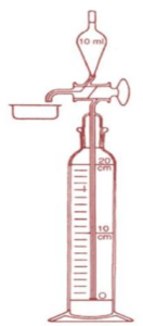
Andreasen Pipette Technique
A much quicker and less-tedious method of sedimentation analysis is the Andreasen Pipette Technique
The method is much quicker than beaker decantation, as samples are taken off successively throughout the test for increasingly finer particle sizes
Elutriation Tanks
Elutriation is a process of sizing particles by means of an upward current of fluid, usually water or air.
Separation of particles in a powder based on the low density of fine particles and high density of the coarse particles using fluid flow
The process is the reverse of gravity sedimentation, and Stokes’ law applies.
All elutriators consist of one or more “sorting columns“ in which the fluid is rising at a constant velocity.

- In case of sedimentation, particles move in the direction of gravitational force
- In case of elutriation, some particles move against the gravitational force
- The arrows are vectors showing direction and magnitude of particle movement
- In sedimentation, fluid is stationary and particle settle based on the particle velocity
- In elutriation, fluid flows in opposite direction of the settling movement

Sedimentation Elutriation
Uses
Applicable to insoluble solids such as kaolin or chalk, which are subjected to wet grinding followed by sedimentation or elutriation
Advantages
– It is a continuous process
– Quick separation of size fractions
– More compact apparatus compared to sedimentation tank
– More number of tubes of different area of cross section can be connected
Disadvantages
The suspension or solids should be diluted, which may be not desirable in certain cases
Static tank method
- The dry powder or paste made by levigation is placed in the tank
- It is mixed with large quantity of water
- The solid particles are distributed uniformly in the liquid during stirring
- Particles are allowed to settle
- Depending on the density, the solid particles may either settle down or remain suspended in water • Sample are withdrawn at different heights through the outlets
- The powders are dried and various size fractions are collected

- Single separation with mobile liquid
- Separation as multiple fractions
Cyclone Separator
Principle
- Centrifugal force is used to separate the solids from fluids. The separation depends not only on the particle size but also on the density of particles.
- Depending on the fluid velocity, this can be used to separate all types of particles. Even fine particles can be carried by the fluid

Construction
- It consists of a short vertical, cylindrical vessel with a conical base
- The upper part of the vessel is filled with a tangential inlet
- The solid outlet is arranged at the base
- Fluid outlet is provided at the center of the top portion, which extends inwardly into the separator • This prevents the air short circuiting directly form the inlet to the outlet of the fluid
Working
- The solids to be separated are suspended in a stream of gas (air)
- The above feed is introduced tangentially at a very high velocity, so that energy movement takes place within the vessel
- The centrifugal force and vortexing throws the solids to the walls
- As the speed of air diminishes, the particles fall to the conical base and are discharged through the solid outlet • The fluid can escape from the central outlet at the top
Uses
Used to separate the solids from gases
Used for size separation of solids in liquids
Used for separating the heavy to coarse fraction from fine dust
Bag Filter
Principle
Size separation of fines or dust from the milled powder is achieved in two steps:
The milled powder is passed through a bag filter by applying the suction on the opposite side of the feed entry which facilitates separation
Pressure is applied in order to shake the bags so that powder adhering to the bag falls off, which is collected from the conical base.

Construction
It consists of a number of bags made of cotton or wool fabric which are suspended in a sheet metal container A hopper is arranged at the bottom of the filter to receive the feed
At the top of the metal container, a provision is made for the exhaust
Adjacent to this, a bell crank lever arrangement is made to bring the filters to normal atmospheric conditions
| Step | Mechanism | Movement of damper Contact between bags and suction | Movement of damper Contact between bags and atmosphere |
| Filtering period | Cam does not press the bell crank lever | Opens | Closes |
| Shaking period | Cam presses the bell crank lever | Closes | Opens |
These changes occur at intervals of a few minutes
Working
Consists of two steps:
Firstly, the feed is separated from air by passing it through the cloth bags
Secondly, the bags are shaken to collect the fines that are adhered to the bags
These two steps follow in succession and are controlled at different intervals with the help of a bell crank lever arrangement
Bell crank lever arrangement
A shaft with a cam is allowed to rotate at a low speed.
During rotation, the cam can either press the bell crank lever or does not come into contact.
Depending on this mechanism, the damper changes its position. The damper is useful mechanism, which allows two steps to occur
Filtering period
- The exhaust positioned at the top keeps the bags under less pressure than atmospheric pressure
- The gas containing fine particles enters the hoper
- The gas feed passes through the fabric of bag
- During this, the fines are retained in the bags, while the gas reaches the top of the casing
Shaking period
- As vacuum is cut off in the chamber, air from outside enters the casing and passes through the bags
- This results in violent shaking of the bags, so that dust and fine particle are displaced from the bags and falls into the conical base.
- It is then removed at intervals
Uses
- Used along with other size separation equipment
e.g., cyclone separator
Bag filter is connected to the discharge end of the fluidized energy mill
Advantages
- It is extremely useful for removing fines, which cannot be separated by other methods
- It can be used to remove dust (ordinary household vacuum cleaner)
Disadvantages
- It is not a size separation equipment as such
Air Separator
Principle
- Centrifugal force is used to separate solids rotating disc and blades
- Stationary blades are used to improve separation
- By controlling these blades and the speed of the rotation, it is possible to vary the size at which separation occurs
Construction
- Consists of a cylindrical vessel with a conical base
- The feed inlet is fitted to upper part of the vessel
- The rotating disc and rotating blades are attached to the central shaft to produce air environment
- At the base of the vessel, two outlets are provided; one for fine particles and the other for heavy particles

Working
- The disc and blades are allowed to rotate by means of a motor. These produce a current of air.
- The sample powder is introduced through the feed inlet which falls on the rotating disc
- The fine particles picked up and carried into space, where air velocity is sufficiently reduced
- The fine particles are dropped and are ultimately collected at the outlet meant for fine particles.
- The heavy particles which fall downward are removed at the outlet meant for heavy particles
Uses
Often attached to ball mill or hammer mill
Summary
- Size separation is an unit operation that involves the separation of a mixture of various sizes of particles into two or more portions by means of screening surface
- Types of separation includes diffusional and mechanical separation
- Sieve number can be defined as the number of meshes present in a linear length of 2.54 cm
- Centrifugal force is used to separate the solids from fluids. The separation depends not only on the particle size but also on the density of particles
- Bag filters are used for removing fines, which cannot be separated by other methods
- In sedimentation technique, the particles move towards the gravitational force and vice-versa in Elutriation technique
For Size Separation Detailed PDF Notes Click on Download Button