Flow of fluids

Intended Learning Outcomes
At the end of this lecture student will be able to:
• Define fluids with its properties
• Differentiate between fluid statics and fluid dynamics
• Recall the applications of Reynolds number
• Discuss the types of energy losses
• Describe the construction and working of simple monometer
• Compare and contrast between the three types of monometers
• Point out the devices used for measuring the rate of flow of fluids
• Explain the principle and working of orifice meter
• Discuss the construction and working of venturi meter
• Differentiate between orifice and venturi meter
• Justify the importance of pitot tube
• Recall the importance of rotameter as a fluid flow measuring device
FLOW of FLUID
A fluid is a substance that continually deforms (flows) under an applied shear stress
Fluids are a subset of the phases of matter and include liquids, gases
Fluid flow may be defined as the flow of substances that do not permanently resist distortion
The subject of fluid flow can be divided into fluid static’s and fluid dynamics
FLUID STATICS
• Fluid static’s deals with the fluids at rest in equilibrium
• Behavior of liquid at rest
• Nature of pressure it exerts and the variation of pressure at different layers
Pressure differences between layers of liquids
Fluid dynamics
• Fluid dynamics deals with the study of fluids in motion
• This knowledge is important for liquids, gels, ointments which will change their flow behavior when exposed to different stress conditions
MIXING
FLOW THROUGH PIPES
FILLED IN CONTAINER
Types of flow
Identification of type of flow is important in
• Manufacture of dosage forms
• Handling of drugs for administration
The flow of fluid through a closed channel can be viscous or turbulent and it can be observed by Reynolds experiment
Glass tube is connected to reservoir of water, rate of flow of water is adjusted by a valve, a reservoir of colored solution is connected to one end of the glass tube with help of nozzle.
Colored solution is introduced into the nozzle as fine stream
Laminar flow is one in which the fluid particles move in layers or laminar with one layer sliding with other. There is no exchange of fluid particles from one layer to other
When velocity of the water is increased the thread of the colored water disappears and mass of the water gets uniformly colored, indicates complete mixing of the solution and the flow of the fluid is called as turbulent flow
The velocity at which the fluid changes from laminar flow to turbulent flow that velocity is called as critical velocity
Reynolds number
In Reynolds experiment the flow conditions are affected by
Diameter of pipe
Average velocity
Density of liquid
Viscosity of the fluid
This four factors are combined in one way as Reynolds number
Reynolds number is obtained by the following equation
D u ρ Inertial forces Mass X Acceleration of liquid flowing
——— = —————————— = ———————————————
η Viscous forces Shear stress x area
- Inertial forces are due to mass and the velocity of the fluid particles trying to diffuse the fluid particles
- Viscous force if the frictional force due to the viscosity of the fluid which make the motion of the fluid in parallel.
- At low velocities the inertial forces are less when compared to the frictional forces
- Resulting flow will be viscous in nature
- Other hand when inertial forces are predominant the fluid layers break up due to the increase in velocity hence turbulent flow takes place.
- If Re < 2000 the flow I said to be laminar
- If Re > 4000 the flow is said to be turbulent
- If Re lies between 2000 to 4000 the flow change between laminar to turbulent
Types of flow
Laminar flow is one in which the fluid particles move in layers or laminar with one layer sliding with other
There is no exchange of fluid particles from one layer to other
Avg. Velosity = 0.5Vmax
Re < 2000
- Turbulent flowis when velocity of the water is increased the thread of the colored water disappears and mass of the water gets uniformly colored
- There is complete mixing of the solution and the flow of the fluid is called as turbulent flow
- Avg velocity = 0.8 Vmax
- Re > 4000
The velocity at which the fluid changes from laminar flow to turbulent flow that velocity is called as critical velocity
Applications
- Reynolds number is used to predict the nature of the flow
- Stoke’s law equation is modified to include Reynolds number to study the rate of sedimentation in suspension
When velocity is plotted against the distance from the wall following conclusions can be drawn
- The flow of fluid in the middle of the pipe is faster than the fluid near to the wall
- Thevelocity of fluid approaches zero as the pipe wall is approached
- At the actual surface of the pipe wall the velocity of the fluid is zero

- The velocity of the fluid is zero at the wall surface there should be some layer in viscous flow near the pipe wall which acts as stagnant layer
- if the flow is turbulent at the center and viscous at the surface a buffer layer exist, this buffer layer changes between the viscous to turbulent flow
Bernoulli’s theorem
- When the principals of the law of energy is applied to the flow of the fluids the resulting equation is called Bernoulli’s theorem
Consider a pump working under isothermal conditions between points A and B
- Bernoulli’s theorem states that in a steady state the total energy per unit mass consists of pressure, kinetic and potential energies are constant

Kinetic energy = u2 / 2g
Pressure energy = Pa / ρAg
- At point a one kilogram of liquid is assumed to be entering at this point, pressure energy at joule can be written as
Pressure energy = Pa /g ρ A
Where Pa = Pressure at point a
g = Acceleration due to gravity
ρ A = Density of the liquid
Potential energy of a body is defined as the energy possessed by the body by the virtue of its position
Potential energy = XA
Kinetic energy of a body is defined as the energy possessed by the body by virtue of its motion,
Kinetic energy = UA2 / 2g
Total energy at point A = Pressure energy + Potential energy + Kinetic energy
Total energy at point A = Pa /g ρ A +XA + UA2/ 2g
According to the Bernoulli’s theorem the total energy at point
A is constant
Total energy at point A = Pa /g ρ A +XA + UA2 / 2g = Constant
After the system reaches the steady state, whenever one kilogram of liquid enters at point A, and another one kilogram of liquid leaves at point B
Total energy at point B = PB /g ρ B + XB + UB2/ 2g
INPUT = OUT PUT
Pa /g ρ A +XA + UA2 / 2g =PB /g ρ B +XB + UB2/2g
Theoretically all kids of the energies involved in fluid flow should be accounted, pump has added certain amount of energy
Energy added by the pump = + wJ
During the transport some energy is converted to heat due to frictional Forces
Loss of energy due to friction in the line = FJ
Pa /g ρ A +XA + UA2 / 2g – F + W = PB /g ρ B +XB + UB2/2g
Applications
- Used in the measurement of rate of fluid flow
- It applied in the working of the centrifugal pump, in this kinetic energy is converted in to pressure.
- Used in the measurement of rate of fluid flow using flowmeters
- It applied in the working of the centrifugal pump, in this kinetic energy is converted in to pressure.
Energy losses
According to the law of conversation of energy, energy balance have to be properly calculated
Fluids experiences energy losses in several ways while flowing through pipes, they are
- Frictional losses
- Losses in the fitting
- Enlargement losses
- Contraction losses
Frictional losses
During flow of fluids frictional forces causes a loss in pressure. Type of fluid flow also influences the losses.
In general pressure drop will be
PRESSURE DROP α VELOCITY (u)
α Density of fluid(ρ)
α Length of the pipe (L)
α 1 / diameter of the pipe (D)
These relationships are proposed in Fanning equation for calculating friction losses
Fanning equation ∆p = 2 fu2Lρ / D
F = frictional factor
For viscous flow pressure drop Hagen –Poiseullie equation = 32 Luη / D2
Losses in fitting
Fanning equation is applicable for the losses in straight pipe. When fitting are introduced into a straight pipe, they cause disturbance in the flow, which result in the additional loss of energy losses in fitting may be due to
- Change in direction
- Change in the type of fittings
Tee fitting Equivalent length = 90
Globe valve equivalent length = 300
Equivalent fitting = Equivalent fitting x internal diameter
For globe valve = 300 x 50 = 15 meter
That means globe valve is equal to 15 meters straight line, so this length is substituted in fanning equation
Enlargement loss
If the cross section of the pipe enlarges gradually, the fluid adapts itself to the changed section without any disturbance. So no loss of energy
If the cross section of the pipe changes suddenly then loss in energy is observed due to eddies. These are greater at this point than straight line pipe
Then u2< u1
For sudden enlargement = ∆ H = u1 – u2 / 2g
∆ H = loss of head due to sudden enlargement
Contraction losses
If the cross section of the pipe is reduced suddenly the fluid flow is disturbed, the diameter of the fluid stream is less than the initial column this point is known as vena contracta
∆Hc = K u22 / 2gc
Where, u2 is the velocity in the smaller cross section and K is a constant, the value of which depends on the relative areas of two sections
Manometers
Manometers are the devices used for measuring the pressure difference
Different type of manometers are there they are
- Simple manometer
- Differential manometer
- Inclined manometer
Simple manometer
- This manometer is the most commonly used one
- It consists of a glass U shaped tube filled with a liquid A- of density
ρA kg /meter cube and above A the arms are filled with liquid B of density ρB
- The liquid A and B are immiscible and the interference can be seen clearly
- If two different pressures are applied on the two arms the meniscus of the one liquid will be higher than the other
- Let pressure at point 1 will be P1 Pascal’s and point 5 will be P2 Pascal’s
- The pressure at point 2 can be written as= P1+ (m + R ) ρ B g
(m + R ) = distance from 3 to 5
Differential manometers
- These manometers are suitable for measurement of small pressure differences
- It is also known as two – Fluid U- tube manometer
- It contains two immiscible liquids A and B having nearly same densities
- The U tube contains of enlarged chambers on both limbs
- Using the principle of simple manometer the pressure differences can be written as
∆P =P1 –P2 =R (ρc – ρA) g
Hence smaller the difference between ρc and ρA larger will be R
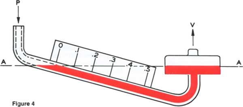
Inclined tube manometers
Many applications require accurate measurement of low pressure such as drafts and very low differentials, primarily in air and gas installations.
In these applications the manometer is arranged with the indicating tube inclined, as in Figure, therefore providing an expanded scale.
This enables the measurement of small pressure changes with increased accuracy.
P1 –P2 = g R (ρ A – ρ B) sin α
Measurement of rate of flow of fluids
Whenever fluid are used in a process it is necessary to measure
The rate at which the fluid is flowing through the pipe
Methods of measurement are
- Direct weighing or measuring
- Hydrodynamic methods
- Orifice meter
- Venturi meter
- Pitot meter
- Rotameter
- Direct displacement meter
Direct weighing or measuring
The liquid flowing through a pipe is collected for specific period at any point and weighed or measured, and the rate of flow can be determined.
Gases cannot be determined by this method
Orifice meter
Principle
- Orifice meter is a thin plate containing a narrow and sharp aperture
- When a fluid stream is allowed to pass through a narrow constriction the velocity of the fluid increase compared toup stream
- This results in decrease in pressure drop and the difference in the pressure may be read from a manometer
- The velocity of the fluid at thin constriction may be written as
U0 =C 0 √ 2g ∆H
∆H = can be measured by manometer
C0 = constant
U0 = velocity of fluid at the point of orifice meter
Construction
- It is consider to be a thin plate containing a sharp aperture through which fluid flows
- Normally it is placed between long straight pipes
- For present discussion plate is introduced into pipe and manometer is connected at points A and B
Working
- Orifice meter is referred as the variable head meter, i.e it measure the variation in the pressure across a fixed construction placed in the path of flow

- When fluid is allowed to pass through the orifice the velocity of the fluid at point B increase, as a result at point A pressure will be increased.
- Difference in the pressure is measured by manometer
- Bernoulli’s equation is applied to point A and point B for experimental conditions
√U02 – UA2 =C0√2g. ∆H
U0 = velocity of fluid at orifice
UA = velocity of fluid at point A
C0 = constant
- If the diameter of the orifice is 1/5 or less of the pipe diameter then UA is neglected
Applications
- Velocity at either of the point A and B can be measured
- Volume of liquid flowing per hour can be determined by knowing the area of the cross section
Venturi meter
- When fluid is allowed to pass through narrow venturi throat then velocity of fluid increases and pressure decreases
- Difference in upstream and downstream pressure head can be measured by using Manometer
U v = C v√ 2g . ∆H

Why Venturi meter if Orifice meter is available?
- Main disadvantage of orifice meter is power loss due to sudden contraction with consequent eddies on other side of orifice plate
- We can minimize power loss by gradual contraction of pipe
- Ventury meter consist of two tapperd (conical section) inserted in pipeline
- Friction losses and eddies can be minimized by this arrangement
Advantage
- Power loss is less
- Head loss is negligible
Disadvantage
- Expensive
- Not flexible it is permanent
- Need technical export
Differences between orifice and venture meter
|
Orifice Meter |
Venture meter |
|
• Cheap • Easy to install • Construction can be made • Head losses are more • Power losses are more, particularly coefficient • Normally used for testing purpose • Greater flexibility • Reading is larger under identical condition |
• Expensive • Fabrication is highly technical • It should be purchased from a dealer • Head losses are insignificant • Power losses are less • Used in online installation • Not flexible ,permanent • The reading is comparatively smaller under |
Pitot Tube
It is also known as insertion tube
The size of the sensing element is small compared to the flow channel
One tube is perpendicular to the flow direction and the other is parallel to the flow
Two tubes are connected to the manometer
∆Hp = u2/2g
U2= velocity of the flow at the point of insertion
∆ HP= difference in head from monometer, m
A pitot tube is a pressure measurement instrument used to measure fluid flow velocity
The pitot tube was invented by the French engineer Henri Pitot in the early 18th century and was modified to its modern form in the mid19th century by French scientist Henry Darcy
It is widely used to determine the airspeed of an aircraft, water speed of a boat, and to measure liquid, air and gas velocities in industrial Applications
The pitot tube is used to measure the local velocity at a given point in the flow stream and not the average velocity in the pipe or conduit

Working
• Tube are inserted in the flow shown is the figure
U2 = Cv √2g. ∆H
• Cv = Coefficient of Pitot tube
Working of Pitot Tube
- A pitot tube is simply a small cylinder that faces a fluid so that the fluid can enter it
- Because the cylinder is open on one side and enclosed on the other, fluid entering it cannot flow any further and comes to a rest inside of the device
- A diaphragm inside of the pitot tube separates the incoming pressure (static pressure) from the stagnation pressure (total pressure) of a system
- The difference between these two measurements determines the fluid’s rate of flow
Advantages:
- Pitot tubes measure pressure levels in a fluid
- They do not contain any moving parts and routine use does not easily damage them
- Also, pitot tubes are small and can be used in tight spaces that other devices cannot fit into
Disadvantages:
- Foreign material in a fluid can easily clog pitot tubes and disrupt normal readings as a result
- This is a major problem that has already caused several aircraft to crash and many more to make emergency landings
Rotameter
Variable area meter
- A device used to measure fluid flow, in which a float rises in a tapered vertical tube to a height dependent on the rate of flow through the tube
- It is a variable area meter which works on the principle of upthurst force exerted by fluid and force of gravity
Construction
- It consists of vertically tampered and transparent tube in which a plummet is placed
- During the flow the plummet rise due to variation in flow
- The upper edge of the plummet is used as an index to note the reading
- Graduated tapered metering glass tube
- Float
Float:
- Floats may be constructed of metals of various densities from lead to aluminum or from glass or plastic.
- Stainless-steel floats are common ones
- Float shapes and proportions are also varied for different applications
- For small flows floats are spherical in shape
Working
- As the flow is upward through the tapered tube the plummet rises and falls depend on the flow rate
- Greater the flow rate higher the rise
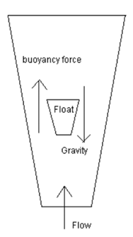
Fluid enters the tapered tube, some of the fluid strikes directly the float. Some of the fluid passes from sides
Two forces are acting in this case:
- Upthurst Force (Buoyancy)
- Weight of the float
Annular space increases due to increase in area of the tube
When equilibrium is established the float comes to rest
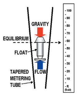
Measurement of flow rate
The flowrate is measured directly from calibrated scale.
The reading is noted generally from ending point of cap of the float.
Advantages:
- No external power or fuel
- Manufactured of cheap materials
- Since the area of the flow passage increases as the float moves up the tube, the scale is approximately linear.
Disadvantages:
- Accuracy of rotameter
- Uncertainty of the measurement
- Impact of gravity
Summary
- A fluid is a substance that continually deforms (flows) under an applied shear stress
- Fluid static’s deals with the fluids at rest in equilibrium
- Fluid dynamics deals with the study of fluids in motion
- The flow of fluid through a closed channel can be viscous or turbulent and it can be observed by Reynolds experiment
- Bernoulli’s theorem states that in a steady state the total energy per unit mass consists of pressure, kinetic and potential energies are constant
- According to the law of conversation of energy, energy balance have to be properly calculated
- Manometers are the devices used for measuring the pressure difference
- Differential manometers are suitable for measurement of small pressure differences
- Inclined monometer enables the measurement of small pressure changes with increased Accuracy
- Orifice meter is referred as the variable head meter, i.e it measure the variation in the pressure across a fixed construction placed in the path of flow
- When fluid is allowed to pass through narrow venturi throat then velocity of fluid increases and pressure decreases
- Main disadvantage of orifice meter is power loss due to sudden contraction with consequent eddies on other side of orifice plate
- A pitot tube is a pressure measurement instrument used to measure fluid flow velocity
- Rotameter is a device used to measure fluid flow, in which a float rises in a tapered vertical tube to a height dependent on the rate of flow through the tube
For PDF Notes Click On Download Button