UV Visible Spectrophotometers Instrumentation
Objectives
At the end of the session students will be able to
• Identify the essential components of UV Visible spectrophotometers
• Explain the construction and working of radiation sources and dispersive devises used in UV- Visible spectrophotometers
UV Visible Spectrophotometer
· Components of spectrophotometers
-
- Sources
- Wavelength selectors (filters, monochromators)
- Sample containers
- Detectors
- Readout devices
- Instrumentation (Spectrophotometers)

A single beam
spectrophotometer
The above essential features of a spectrophotometer shows that polychromatic light from a source separated into narrow band of wavelength (nearly monochromatic light) by a wavelength selector, passed through
the sample compartment and the transmitted intensity, P, after the sample is measured by a detector
In a single beam instrument, the light beam follows a single path from the source, to the monochromator, to the sample cell and finally to the detector
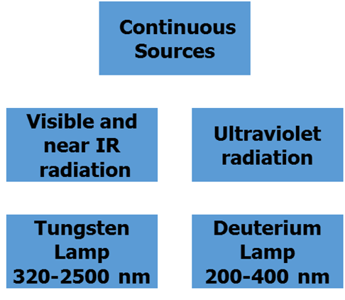
1- Sources of light
Sources used in UV-Vis Spectrophotometers are continuous sources.
• Continuous sources emit radiation of all wavelengths within the spectral region for which they are to be used.
• Sources of radiation should also be stable and of high intensity.

2. Wavelength Selectors
Ideally the output of a wavelength selector would be a radiation of a single wavelength.
No real wavelength selector is ideal, usually a band of radiation is obtained.


The narrower this bandwidth is , the better performance of the instrument.
Wavelength selectors for spectrometry
| Type | Wavelength range (nm) | Note |
| Continuously variable | ||
| Grating | 100 ~ 40,000 | 3000 lines/mm for vacuum UV,
50 lines/mm for far IR |
| Prism | 120 ~ 30,000 | |
| Discontinuous | ||
| Interference filter | 200 ~ 14,000 | |
| Absorption filter | 380 ~ 750 |
 |
Dispersion of radiation along the focal plane AB of a typical prism(a) and echellette grating (b).

Schematic diagram of diffraction from a grating.
nl = (a– b)
d sin q= a
– d sin f= b
nl = d (sin q + sin f )
i- Filters
• Filters permit certain bands of wavelength (bandwidth of ~ 50 nm) to pass through.
• The simplest kind of filter is absorption filters , the most common of this type of filters is colored glass filters.
• They are used in the visible region.
• The colored glass absorbs a broad portion of the spectrum (complementary color) and transmits other portions (its color).
Disadvantage
• They are not very good wavelength selectors and can’t be used in instruments utilized in research.
• This is because they allow the passage of a broad bandwidth which gives a chance for deviations from Beer’s law.
• They absorb a significant fraction of the desired radiation.

(a) Schematic cross section of an interference filter.
(b) Schematic to show the conditions for constructive interference

Transmission spectra of interference filters.
(a) Wide band pass filter has ~90% transmission in the 3- 50 5- mm wavelength range but <0.01% transmittance outside this range.
(b) Narrow band-pass filter has a transmission width of 0.1 mm centered around 4 mm.
Complimentary colours – selection of filters

ii- Monochromators
ØThey are used for spectral scanning (varying the wavelength of radiation over a considerable range ).
ØThey can be used for UV/Vis region.
ØAll monochromators are similar in mechanical construction.
ØAll monochromators employ slits, mirrors, lenses, gratings or prisms.

1-Grating monochromators
Reflection grating
M Polychromatic radiation from the entrance slit is collimated (made into beam of parallel rays) by a concave mirrors
M These rays fall on a reflection grating, whereupon different wavelengths are reflected at different angles.
M The orientation of the reflection grating directs only one narrow band wavelengths, l2, to the exit slit of the mono-chromator
M Rotation of the grating allows different wavelengths, l1, to pass through the exit slit

The reflection grating monochromator Device consists of entrance and exit slits, mirrors, and a grating to disperse the light
Echellette Reflection Grating
1.The reflection grating is ruled with a series of closely spaced, parallel grooves with repeated distance d.
2.The grating is covered with Al to make it reflective.
3.When polychromatic light is reflected from the grating, each groove behaves as a new point source of radiation.
4.When adjacent light rays are in phase, they reinforce one another (constructive interference).
5.When adjacent light rays are not in phase, they partially or completely canceled one another (destructive interference).


Reflection followed by either constructive or destructive interferences


Note: For more detail see Skoog text book p. 159-160
Echellette Grating equation
• n l = d (sin qi + sin qr)
where n = 1, 2, 3,….
• Since incident angle qi = constant; therefore l µ qr
• For each reflection angle qr , acertain wavelength is observed
2- Prism monochromators
G Dispersion by prism depends on refraction of light which is wavelength dependent
A Violet color with higher energy (shorter wavelength) are diffracted or bent most
B While red light with lower energy (longer wavelength are diffracted or bent least
FAs a result, the poly-chromatic white light is dispersed to its individual colors


The advantages and disadvantages of decreasing monochromator slit width
The size of the monochromator exit slit determines the width of radiation (bandwidth) emitted from the monochromator.
A widerslit width gives higher sensitivity because higher radiation intensity passes to the sample but on the other hand, narrowslit width gives better resolution for the spectrum.
In general, the choice of slit width to use in an experiment must be made by compromising these factors. Still, we can overcome the problem of low sensitivity of the small slit by increasing the sensitivity of the detector.

Bandwidth Choice
3- Sample compartment (cells)
Ø For Visible and UV spectroscopy, a liquid sample is usually contained in a cell called a cuvette.
Ø Glass is suitable for visible but not for UV spectroscopy because it absorbs UV radiation. Quartz can be used in UV as well as in visible spectroscopy

4- Detectors
$ The detectors are devices that convert radiant energy into electrical signal.
$ A Detector should be sensitive, and has a fast response over a considerable range of wavelengths.
$ In addition, the electrical signal produced by the detector must be directly proportional to the transmitted intensity (linear response).
i- Phototube
![]() Phototube emits electrons from a photosensitive, negatively charged cathode when struck by visible or UV radiation
Phototube emits electrons from a photosensitive, negatively charged cathode when struck by visible or UV radiation
![]() The electrons flow through vacuum to an anode to produce current which is proportional to radiation intensity.
The electrons flow through vacuum to an anode to produce current which is proportional to radiation intensity.

a) Barrier-layer photocell:

Barrier layer cell
one of the simplest detectors, which has the advantage that it requires no power supply but gives a current, which is directly proportional to the light intensity. It is consists of a metallic plate, usually copper or iron, upon which is deposited a layer of selenium.
An extremely thin transparent layer of a good conducting metal, e.g. silver, platinum or copper, is formed over the selenium to act as one electrode, the metallic plate acting as the other. Light passes through the semitransparent silver layer causes release of an electron, which migrates, to the collector.
The electron accumulating on the collector resulting in a potential difference between the base and collector, which can be measured by a low resistance galvanometer circuit.
The useful working range of selenium photocell is 380-780 nm. Their lack of sensitivity compared to phototube and photo multiplier tube, restricts their use to the cheapest colorimeters and flame photometers.
b) Photo emissive tube:
It consists of an anode and a cathode sealed in an evacuated glass tube, which may have a quartz or silica window for UV measurement.

Photo emissive tube:
The cathode is coated with a layer of light sensitive material that emits electrons upon absorption of photons.
A power supply maintains the anode positive with respect to the cathode so that the photoelectrons are collected at the anode.
This current is directly proportional to the light intensity. Phototubes are available for use over the entire UV/visible region of the spectrum, but no single tube covers the entire range satisfactorily.
Therefore many instruments with phototube detectors employ interchangeable blue and red sensitive phototube in order to provide sufficient sensitivity over the entire spectrum.
c) Photo multiplier tube:

It is very sensitive detector with very short response times. It contains a photo cathode and a series of dynodes, which are also photosensitive.

Phototube


Schematic diagram
of photomultiplier with nine dynodes.
ii. Photomultiplier tube
Ø It is a very sensitive device in which electrons emitted from the photosensitive cathode strike a second surface called dynode which is positive with respect to the original cathode.
Ø Electrons are thus accelerated and can knock out more than one electrons from the dynode.
Ø If the above process is repeated several times, so more than 106 electrons are finally collected for each photon striking the first cathode.

Photo Diode

Schematic diagram of Photo Diode Array

The components of a single beam spectrophotometer


Summary
• A typical spectrophotometer consists of radiation sources, dispersive devise, sample compartment, detector and read out system
• Visible radiation sources area tungsten lamp or halogenated tungsten lamp
• UV radiation sources include a Hydrogen or deuterium discharge lamp
• Filters, prisms and gratings constitute dispersive devises
• Cuvettes are sample holders. They can be cylindrical or rectangular.
• Detectors can be a barrier layer cell, a photo cell, a photo multiplier tube, a diode or diode array detector
• Single beam, double beam and diode array spectrophotometers are available in the market
For PDF Notes Click on Download Button
